RETURN TO INDEX PAGE
Syncal - The Racal TRA921 and TRA931 Transceivers
by Keith Thrower
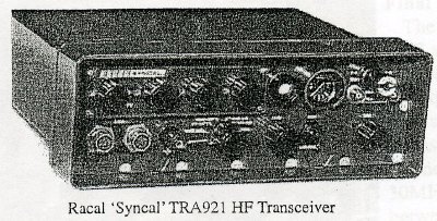
The TRA921 'Syncal' was Racal's first HF manpack to have synthesised
control of its operating frequency and followed directly from the huge
success of 'Squadcal' described in our last issue. The history of its origin
is of interest; the British Government had placed contracts with BCC, Plessey
and GEC for the development of the Clansman range of tactical HF and VHF
radios for re equipping the British Army. The contract with Plessey was
for HF manpack radios with synthesiser frequency control and for this Plessey
had developed a thick film module. Racal had approached Plessey to see
if they could purchase this for use in a new HF manpack for sales to Third
World countries, but the price quoted was around 300 and this did not include
the additional cost of engineering the module into a fully working 'frequency
synthesiser capable of use in both the transmit and receive modes.
 At
the time I had just completed the design of a programmable frequency synthesiser
for use with a large HF communications system that had been sold to the
Royal Canadian Air Force. This was a large piece of rack mounted equipment
to cover the full HF band up to 30MHz and was based on analogue techniques
throughout and not at all capable of adaptation for manpack use where low
power consumption and compact construction were essential.
At
the time I had just completed the design of a programmable frequency synthesiser
for use with a large HF communications system that had been sold to the
Royal Canadian Air Force. This was a large piece of rack mounted equipment
to cover the full HF band up to 30MHz and was based on analogue techniques
throughout and not at all capable of adaptation for manpack use where low
power consumption and compact construction were essential.
In mid 1966 I attended a meeting with the then Racal Chairman and founder
of the company, Ray Brown (later Sir Raymond Brown), when the dilemma facing
the company with its desire to produce a lowcost synthesised manpack radio
to cover the frequency band of 28MHZ in steps of 1kHz. I made the somewhat
rash statement that "It should be possible to produce a frequency synthesiser
for less than £300. The Chairman immediately said "Go away and come
back tomorrow morning and tell me how you propose to do this". Needless
to say I had no sleep that night and worked through goodness knows how
many sheets of paper to find a basic design for the frequency synthesiser.
It so happened that the Fairchild Company had just produced a programmable
decade digital divider in integrated circuit form. The only problem was
that it had a maximum operating frequency of only 2MHz. However, this was
an important start and with this I was able to come up with a basic scheme
that had every chance of meeting the important design criteria for the
synthesiser of low cost, small size, low power consumption, and capable
of operating over the required frequency band (more of this later).
A team was then set up to commence design of the radio with Jim Diggins
responsible for the basic radio, assisted by John Killeen. I was responsible
for the design of the frequency synthesiser and was assisted by Alan Cox.
As prime design aims the marketing department had requested that the
radio should have a selling price competitive with Plessey, Redifon, Thomson,
Tadiran and Hughes. It had to be very reliable and given the likely applications
in hostile environments, it needed to be easy to operate (this was because
many of the users were likely to be poorly trained) easy to maintain and
capable of use both as a manpack or in mobile installations.
The final design was mounted in a fully sealed ABS plastic case with
separate clip-on battery pack, and in its manpack form weighed only 4.5kg
(l0lb). It covered the frequency range of 2 to 7.999MHz in 6000 channel
steps of 1kHz, each locked to a precision quartz crystal frequency standard.
Its operating modes were single sideband (upper or lower) and AM, and could
be used for speech or Morse. The transmitter was capable of an output power
of 20watts PEP. There were four rotary switches for selection of frequency
to give the MHz and kHz steps. In addition there was one control for optimum
tuning of the main RF inductor in the inbuilt aerial tuning unit.
The radio consisted of two main units in addition to the battery pack.
These were the Transceiver Unit Type MA924 and the Synthesiser Unit Type
MA920D.
Transceiver Unit
The transceiver was of conventional superheterodyne design with an intermediate
frequency of 10.7MHz. The aerial tuning was by a large coil whose inductance
was varied by a pair of ferrite cores that ran through the centre of the
coil on a threaded screw and connected to a front panel control.
In the transmit mode the speech from the microphone was first amplified
and then passed through an amplitude clipper to a balanced modulator to
provide a double sideband suppressed carrier IF signal centred on 10.7MHz.
Depending upon the required transmission mode, the signal was then passed
to one of an upper sideband filter or lower sideband filter and then to
a double sideband filter (for AM, suppressed carrier, the signal bypassed
the two sideband filters and went, instead, directly to the double sideband
filter). For Morse operation, a 1kHz tone was used as the modulating signal,
with the tone switched on and off by action of the key; the keyed signal
was then passed through one or other of the sideband filters.
The filtered output was then mixed with the local oscillator frequency
(in the range 12.7 to 18.699MHz and then through a low pass filter, which
selected the required transmission frequency in the range 2 to 7.999MHz.
(For example if the required transmission frequency was 4.5MHz the local
oscillator would be set to 15.2MHz, giving 15.2MHz 10.7MHz = 4.5MHz.)
"The signal was then amplified and passed to the aerial tuning unit which
was adjusted to give a peak reading on a meter). The power amplifier could
be operated either on low power (5watts pep), or high power (20 watts pep).
On receive the signal from the aerial was converted down to the 10.7MHz
intermediate frequency by mixing it with the local oscillator frequency,
it then passed through the appropriate filter for LSB, USB or AM and thence
to a balanced modulator supplied with a 10.7MHz crystal derived frequency,
and finally, via an amplifier, to the headphones.
The only active components in the transceiver were transistors and diodes.
There were no integrated circuits.
Synthesiser Unit
At the time the Syncal radio was designed I was not aware of any manpack
radio in production that had synthesiser control, and, for me, it was no
small challenge to find a viable design.
As I mentioned earlier it so happened that Fairchild had just put on
the market programmable decade dividers, but these were limited to a maximum
operating frequency of 2MHz.
I decided, therefore, to adopt the design shown in the block diagram
which consisted of seven principal circuit elements: a varactor diode tuned
local oscillator covering the required frequency range of 12.7 to 18.699M.Hz;
a mixer to reduce the output to the range 0.7 to 1.699MHz; a bank of six
crystal oscillators of frequencies 12, 13, 14, 15 16 and 17MHz respectively;
a variable digital divider using three of the Fairchild integrated circuits
and adjustable from a ratio of 700 to 1699 to give a 1kHz output when phase
lock occurred; a master 5MHz frequency standard; a reference generator
driven from the frequency standard, with outputs frequencies of 10.7MHz.
1MHz and 1kHz; and a sample and hold phase detector whose output was suitably
filtered and used to phase lock the varactor tuned local oscillator.
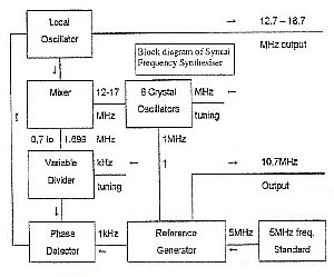
The 10.7MHz output was used for the modulators in the transceiver,
the 1MHz output was used to lock the frequency of the six crystal oscillators
and the 1kHz output was used as the reference frequency for the phase detector.
When overall phase lock occurred the output frequency from the variable
divider had to be exactly equal to that of the 1kHz reference, but the
phase difference between the two inputs would .depend on the required voltage
to suitably tune the oscillator. As an example, if the required local oscillator
frequency was 15.2MHz (corresponding to a transceiver receive or transmit
frequency of 4.5MHz), then the appropriate crystal oscillator frequency
would be 14MHz and the output from the mixer would be 1.2MHz. Thus the
variable divider would have to be set to a ratio of 1200.
The sample and hold phase detector used a field effect transistor and
the output voltage was stored between each sample in a capacitor (this
was to prevent 10.7MHz any 1kHz pulses appearing at the output which would,
otherwise, frequency modulate the oscillator.
At this time (1966) there was almost nothing published on the design
of phase locked oscillators with sampled types of phase detectors so we
had to derive the theory from scratch. It was necessary to keep the overall
loop bandwidth as high as possible to ensure reasonably fast control of
frequency between each selected step and to help minimize oscillator noise.
Another major problem was to avoid any feedback of the fast digital edges
in the synthesiser from finding their way into the transceiver unit. which
would otherwise play havoc with its performance.
As a small sideline the actual production cost of the synthesiser unit
soon fell below £70 quite a saving on the original target of £300.
Final design and further developments
The radio finally went into production in 1967 and was available on
the market in the following year. Like its predecessor, the Squadcal, it
was a major success with total sales of approximately 10,000.
Customer feedback indicated a need to extend the frequency range to
cover 1.6 to 30MHz and to provide interpolation between the 1kHz steps
in order to accommodate less stable receivers. There was also a requirement
for high power mobile and fixed stations. These requirements led to a new
radio named 'Syncal 30' and given the Racal type reference TRA931.
By the late 1960s, new and improved variable digital divider ICs had
become available, together with high power transistors capable of operating
efficiently up to 30MHz. The TRA931 was first produced in 1971 and covered
the 1.6 to 30MHz band in 284,000 channels spaced at 1kHz. Its frequency
stability was better than 2 ppm over the operating temperature range of
25C to +55C. Like the TRA921, it had a single antenna tuning control, but
its inductance was varied by a very clever system of winding the turns
on and off the coil former onto a metallic shorting drum. A search control
allowed fine tuning between the 1kHz steps.
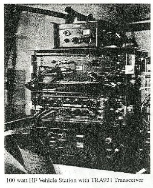
The TRA931 had a maximum output power of 20watts pep and 5watts in low
power. For vehicle and fixed station applications there were 100watt and
400 watt power amplifiers, together with various others ancillary units.
The photograph shows a 100watt vehicle station.
Variants included a frequency hopping version, the TRA931XH, and the
TRA931P with eight programmable channels.
Altogether 58,000 TRA931s were supplied worldwide, including several
thousand in kit form manufactured in Egypt at the Katron factory near Cairo.
Except, perhaps, for the WW1I 19 Set, the TRA931 was the most successful
HF military transceiver ever made. This, together with the earlier Squadcal
and TRA921. were instrumental in the Racal success story.
END OF PAPER
Notes:
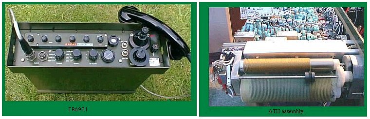
Like the TRA921 the TRA931 had a single antenna tuning control, but
its inductance was varied by a very clever system of winding the turns
on and off the coil former onto a metallic shorting drum. (This 'single
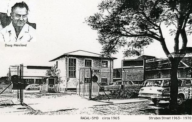
knob antenna tuning control' concept was a RACAL-SMD development and the
first prototype was made by Doug Marsland. To keep the coil wire tension
constant a 'rollup blind' spring was located inside the metallic shorting
drum)
Defence Electronics History Society
Studland House, 12 Christchurch Road Bournemouth, BH1 3NA
Tel: 01202 503879 Fax: 01202 503797
Email: histru@bournemouth.ac.uk
or visit the website at http://histru.bournemouth.ac.uk
RETURN TO INDEX PAGE